Arduino Example Code
const int encoderPin = 2;
volatile unsigned long pulseCount = 0;

void countPulse() {
  pulseCount++;
}

void setup() {
  Serial.begin(9600);

  pinMode(encoderPin, INPUT);
  attachInterrupt(digitalPinToInterrupt(encoderPin), countPulse, FALLING);
}

void loop() {

  pulseCount = 0;

  delay(1000); // Count pulses for 1 second

  Serial.print("Pulses per Second: ");
  Serial.println(pulseCount);

}
Typical Wiring
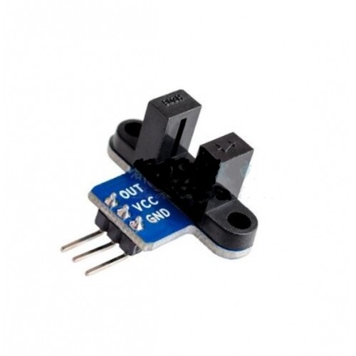
Module VCC -> Arduino 5V
Module GND -> Arduino GND
Module OUT -> Arduino Digital Pin 2
Calculating RPM
If using an encoder disc with a known number of slots, the motor speed can be calculated using the following formula:
RPM = (Pulse Count × 60) ÷ Number of Slots
For example, if an encoder wheel has 20 slots and the sensor detects 100 pulses in one second:
RPM = (100 × 60) ÷ 20 = 300 RPM
Common Applications
- Motor speed measurement
- Rotary encoder projects
- Robot wheel speed sensing
- Conveyor belt monitoring
- Object counting systems
- Industrial automation projects
- Arduino and STEM education projects
Usage Tips
For reliable operation, ensure that the encoder disc or object passes cleanly through the sensor gap without touching the module. Excessive vibration or misalignment can result in missed or false pulses.
Keep the optical gap free from dust and debris, as contamination can reduce sensor performance and affect measurement accuracy.



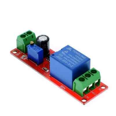
 Arduino Modules & Sensors
 Battery Compartments
 Component Cases
 Electronics Kits
 Microcontroller Boards
 Project Enclosures
 Shields & Hats
 Tablets
 Laptops
 Laptop Accessories
 CPU (Processor)
 CPU Coolers
 GPU (Graphics)
 HDD/ SSD (Storage)
 MOBO (Motherboard)
 PSU (Power Supply)
 RAM (Memory)
 Keyboard & Mouse Combo
 Keyboards
 Printers
 USB