How the Voltage Sensor Module Works
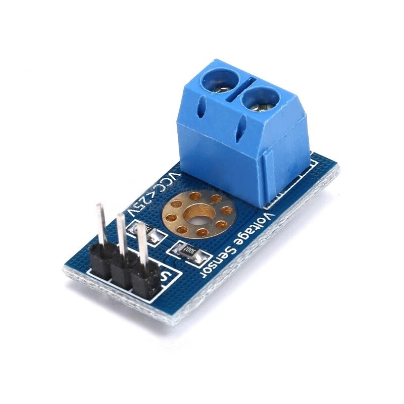
Most 0–25V voltage sensor modules use a pair of resistors to reduce the input voltage before it reaches the analogue output pin.
Measured DC Voltage
        |
        v
Resistor Divider
        |
        v
Reduced Analogue Voltage
        |
        v
Arduino Analogue Input
A commonly used version divides the input voltage by approximately 5, allowing an input of around 25V to produce approximately 5V at the sensor output.
25V Input
   |
   v
Voltage Divider
   |
   v
Approximately 5V Output
Typical Connections
These modules commonly provide a screw terminal for the voltage being measured and a three-pin output header for connection to a microcontroller.
Measured Voltage + -> Sensor Terminal +
Measured Voltage - -> Sensor Terminal -

Sensor S / OUT     -> Arduino A0
Sensor - / GND     -> Arduino GND
Some boards include an additional unused positive header pin because the module itself is passive and does not require a separate power supply. Always follow the labels printed on your particular board.
Important: Common Ground
The negative side of the voltage being measured normally needs to share a common reference with the Arduino ground.
Battery / Supply -
        |
        +------ Sensor GND
        |
        +------ Arduino GND
This means the common low-cost voltage divider module is not electrically isolated. Do not use it where galvanic isolation is required.
Arduino Example Code
const int voltagePin = A0;

void setup() {

  Serial.begin(9600);
}

void loop() {

  int rawValue = analogRead(voltagePin);

  float sensorVoltage =
    rawValue * (5.0 / 1023.0);

  float inputVoltage =
    sensorVoltage * 5.0;

  Serial.print("Voltage: ");
  Serial.print(inputVoltage, 2);
  Serial.println(" V");

  delay(500);
}
This example assumes an Arduino with a 5V ADC reference and a voltage divider ratio of approximately 5:1.
Understanding the Calculation
A classic Arduino Uno or Nano uses a 10-bit analogue-to-digital converter, producing values from 0 to 1023.
ADC Reading:

0    -> Approximately 0V
1023 -> Approximately 5V
The measured voltage at the Arduino pin can therefore be calculated using:
float sensorVoltage =
  rawValue * (5.0 / 1023.0);
If the module divides the input by approximately five, multiply the result by five to estimate the original input voltage.
float inputVoltage =
  sensorVoltage * 5.0;
Example Measurement
Arduino Analogue Input = 2.40V

Voltage Divider Ratio ≈ 5:1

Estimated Input Voltage:

2.40V × 5 = 12.00V
This makes the module convenient for monitoring common 12V batteries and DC power systems.
Improving Measurement Accuracy
The actual resistor values on low-cost modules have manufacturing tolerances, and the Arduino's supply voltage may not be exactly 5.00V. As a result, calculated readings may differ slightly from a calibrated multimeter.
You can improve accuracy by comparing the Arduino reading with a reliable multimeter and applying a calibration factor in software.
float calibration = 1.025;

inputVoltage =
  inputVoltage * calibration;
Adjust the calibration factor until the displayed reading closely matches the reference measurement.
Using an Actual ADC Reference Voltage
Instead of assuming the Arduino analogue reference is exactly 5.00V, measure the actual supply or reference voltage and use that value in your calculation.
float referenceVoltage = 4.96;

float sensorVoltage =
  rawValue * (referenceVoltage / 1023.0);
This can noticeably improve measurement accuracy in battery monitoring and power supply projects.
Example: 12V Battery Monitor
The module can be connected across a 12V battery to allow an Arduino to continuously monitor battery voltage.
12V Battery +
      |
      v
Voltage Sensor +

Voltage Sensor OUT
      |
      v
Arduino A0

12V Battery -
      |
      +------ Voltage Sensor GND
      |
      +------ Arduino GND
Battery Voltage Warning Example
const int voltagePin = A0;

void setup() {

  Serial.begin(9600);
}

void loop() {

  int rawValue = analogRead(voltagePin);

  float voltage =
    rawValue * (5.0 / 1023.0) * 5.0;

  Serial.print("Battery: ");
  Serial.print(voltage, 2);
  Serial.println(" V");

  if (voltage < 11.5) {
    Serial.println("LOW BATTERY WARNING");
  }

  delay(1000);
}
The correct low-voltage threshold depends on the battery chemistry, load and application, so the example value should not be treated as a universal battery protection setting.
Using the Module with ESP32
Extra care is required when using a typical 0–25V module with an ESP32 because ESP32 analogue inputs operate at lower voltages than a 5V Arduino.
A standard module designed to produce up to approximately 5V from a 25V input can exceed the safe input level of an ESP32 GPIO.
25V Input
   |
   v
Typical 5:1 Divider
   |
   v
Up to Approximately 5V

NOT suitable for direct connection
to a 3.3V ESP32 analogue input.
For ESP32 projects, either limit the maximum measured voltage accordingly or use a resistor divider designed to keep the analogue output within the ESP32's safe ADC input range.
Maximum Input Voltage
The commonly advertised 0–25V range assumes a 5V analogue input system and the typical resistor-divider ratio used by these modules.
Do not exceed the voltage range supported by the module or the maximum safe voltage of the connected microcontroller ADC.
Measuring Solar Panel Voltage
A voltage sensor module can also be used to monitor the output of a small solar system.
Solar / Battery Voltage
        |
        v
Voltage Sensor Module
        |
        v
Arduino
        |
        v
LCD / Data Logger / Alarm
This can be combined with a current sensor to calculate approximate electrical power.
Power (W) = Voltage (V) × Current (A)
Common Applications
- 12V battery monitoring
- DC power supply monitoring
- Solar power projects
- Battery voltage alarms
- Automotive electronics experiments
- Arduino data logging
- Power monitoring systems
- Robotics projects
- Bench power supply projects
- UPS and backup power monitoring
- STEM electronics projects
Important Safety Limitation
This type of module is intended for low-voltage DC measurement. It should not be used to directly measure mains AC voltage.
The simple resistor-divider circuit provides no electrical isolation between the measured voltage and the microcontroller.
Important Usage Tips
Confirm polarity before connecting the module and always verify the measured voltage with a multimeter when first testing your project.
For the most accurate results, determine the actual divider ratio of your module and calibrate the software against a known voltage reference.
Remember that the advertised 25V maximum is tied to the analogue input voltage supported by the connected controller. A module that is appropriate for a 5V Arduino may require modification or a different divider ratio when used with a 3.3V microcontroller.



 Arduino Modules & Sensors
 Battery Compartments
 Component Cases
 Electronics Kits
 Microcontroller Boards
 Project Enclosures
 Shields & Hats
 Tablets
 Laptops
 Laptop Accessories
 CPU (Processor)
 CPU Coolers
 GPU (Graphics)
 HDD/ SSD (Storage)
 MOBO (Motherboard)
 PSU (Power Supply)
 RAM (Memory)
 Keyboard & Mouse Combo
 Keyboards
 Printers
 USB