No Arduino Required
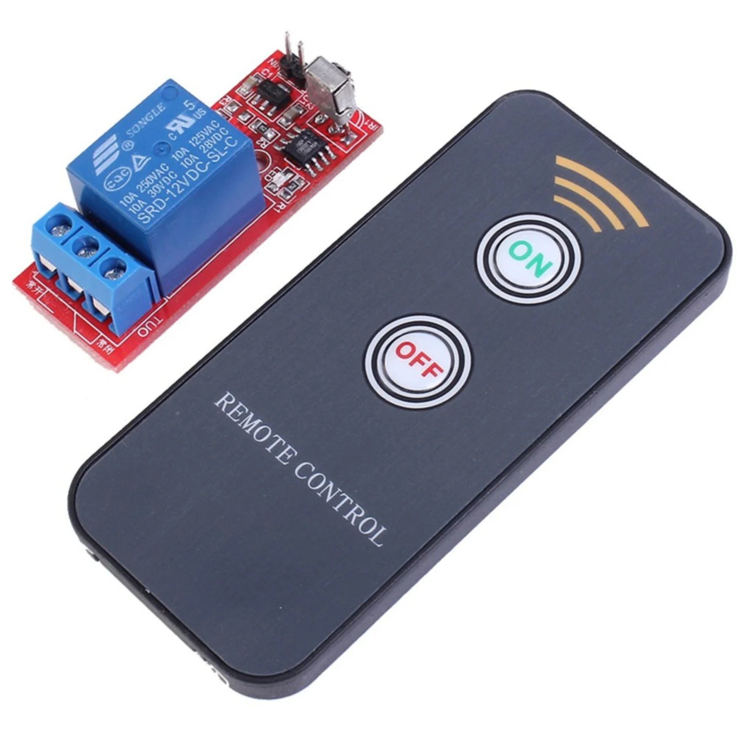
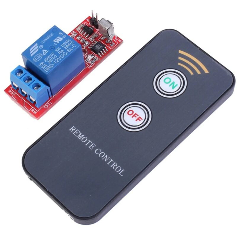
The IR receiver and relay control circuitry are built directly into the module. Once connected to the correct DC supply, a compatible infrared remote can be used to operate the relay without any programming.
5V and 12V Versions
These modules are commonly available in different supply-voltage versions. Always check the voltage markings on your particular module before connecting power.
5V Module  -> Use a suitable 5V DC supply

12V Module -> Use a suitable 12V DC supply
Do not assume that a 5V version can tolerate a 12V supply. Applying excessive voltage may permanently damage the IR receiver or control circuitry.
How the IR Remote Control Works
The onboard infrared receiver detects commands transmitted by a compatible IR remote. The control circuitry then changes the state of the relay according to the operating mode supported by the particular module.
IR Remote
    |
    v
Infrared Signal
    |
    v
IR Receiver
    |
    v
Control Circuit
    |
    v
Relay
    |
    v
Electrical Load
Infrared control generally requires a reasonably clear line of sight between the remote and receiver. Walls and other solid objects normally prevent the IR signal from reaching the module.
Understanding the Relay Connections
The output relay normally provides three switching terminals: COM, NO and NC.
- COM (Common) – the main switching connection.
- NO (Normally Open) – disconnected from COM while the relay is inactive and connected when the relay activates.
- NC (Normally Closed) – connected to COM while the relay is inactive and disconnected when the relay activates.
Example: Switching a DC Light
If the light should normally remain off and switch on when the relay is activated, connect it through the Normally Open (NO) contact.
Load Power Supply +
        |
        v
     Relay COM

     Relay NO
        |
        v
      Light +

      Light -
        |
        v
Load Power Supply -
When the relay activates, COM connects to NO and completes the circuit to the light.
Using the Normally Closed Output
The NC terminal can instead be used when the connected device should normally remain powered and switch off when the relay activates.
Load Power Supply + -> Relay COM
Relay NC -----------> Device +
Device - ------------> Load Power Supply -
The Relay Contacts Are Separate from the Module Supply
The voltage used to power the relay module does not necessarily have to be the same as the voltage being switched by the relay contacts.
For example, a 5V relay control module may be able to switch a separate 12V DC circuit, provided the voltage and current remain within the ratings of the fitted relay and the module PCB.
5V Supply
    |
    +------> IR Relay Module

Separate 12V Supply
    |
    +------> Relay COM
                 |
                 NO
                 |
                 v
              12V Load
Common Relay Operating Modes
Depending on the particular version, IR relay modules may support one or more operating modes such as toggle, momentary or separate ON/OFF control.
Toggle / Latching Operation
Remote Press -> Relay ON

Remote Press -> Relay OFF

Remote Press -> Relay ON
This mode is useful for remotely switching lights, fans and other devices that should remain in their selected state.
Momentary Operation
Remote Command
      |
      v
Relay Activates
      |
      v
Relay Releases
Momentary operation can be useful for door releases, trigger circuits and other applications requiring only a temporary relay activation.
The exact operating modes and remote-button behaviour depend on the controller fitted to your particular module, so test its operation before connecting critical equipment.
Using the Module with Pumps and Solenoid Valves
The relay can be used to control compatible DC pumps, motors and solenoid valves, provided their electrical requirements are within the relay's switching capability.
Power Supply + -> Relay COM
Relay NO ------> Pump / Solenoid +
Pump / Solenoid - -> Power Supply -
Motors, pumps and solenoids are inductive loads and can generate voltage spikes when switched off. Appropriate suppression, such as a flyback diode across a DC inductive load, can help protect the relay contacts and surrounding electronics.
Relay Current Ratings
Check the voltage and current ratings printed on the relay fitted to your particular module before connecting a load. Motors, pumps and other inductive devices can draw considerably more current during startup than during normal operation.
For loads approaching or exceeding the practical capability of the onboard relay, use the module to operate a suitably rated external relay or contactor rather than switching the high-current load directly.
Common Applications
- Remote-controlled lighting
- Fans and ventilation systems
- Small pumps
- Solenoid valves
- Electronic locks and releases
- Workshop automation
- Remote equipment switching
- Robotics projects
- DIY home automation
- Arduino and electronics projects
- STEM education and experiments
IR Remote Range and Positioning
For reliable operation, position the infrared receiver where it has a clear view of the remote control. Direct sunlight, very bright lighting, excessive distance and physical obstructions can reduce IR reception reliability.
Unlike RF remote controls, infrared normally requires the remote to be pointed generally toward the receiver.
Important Usage Tips
Always confirm whether you have the 5V or 12V version before applying power, and verify the module's power-input polarity from the PCB markings.
Test the remote functions and determine whether the relay uses toggle, momentary or another operating mode before connecting equipment that could move, pump liquid or otherwise create a hazard if unexpectedly activated.
When switching mains-voltage equipment, appropriate electrical enclosures, insulation, fusing, wiring and clearances are required. Mains-voltage wiring should only be undertaken by appropriately qualified persons where required.



 Arduino Modules & Sensors
 Battery Compartments
 Component Cases
 Electronics Kits
 Microcontroller Boards
 Project Enclosures
 Shields & Hats
 Tablets
 Laptops
 Laptop Accessories
 CPU (Processor)
 CPU Coolers
 GPU (Graphics)
 HDD/ SSD (Storage)
 MOBO (Motherboard)
 PSU (Power Supply)
 RAM (Memory)
 Keyboard & Mouse Combo
 Keyboards
 Printers
 USB