Important: This Module Is Not the Battery Charger
The XH-M603 should be used with a suitable charger designed for the battery chemistry being charged. The module monitors battery voltage and switches the charger connection, but it does not replace the charger's required constant-current, constant-voltage, or battery-specific charging functions.
For example, a lithium battery should still be connected to an appropriate lithium battery charger, while lead-acid batteries should use a charger designed for the applicable lead-acid battery type.
How Automatic Charge Control Works
The controller uses two voltage settings to determine when charging should start and stop.
Battery voltage falls to lower threshold
              |
              v
        Charging STARTS
              |
              v
      Battery voltage rises
              |
              v
Battery reaches upper threshold
              |
              v
        Charging STOPS
This creates an automatic charging window. Once configured, the controller can repeatedly switch the charger as the battery voltage rises and falls.
Example Charging Configuration
As a simplified example, a compatible battery system might be configured so that charging begins when battery voltage falls to a chosen lower threshold and stops when it reaches a chosen upper threshold.
Lower Threshold -> Start Charging
Upper Threshold -> Stop Charging
The actual voltages you should use depend on the battery chemistry, battery configuration, manufacturer specifications, charger type, and intended application. Do not copy generic voltage values without confirming they are suitable for your battery.
Typical Connection Concept
Suitable Battery Charger
        |
        v
    XH-M603 Relay
        |
        v
      Battery

Battery Voltage
        |
        +-------> XH-M603 Voltage Monitoring
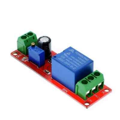
Always check the terminal markings printed on your particular XH-M603 board before connecting power. Module revisions and terminal layouts can vary between manufacturers.
Setting the Charge Thresholds
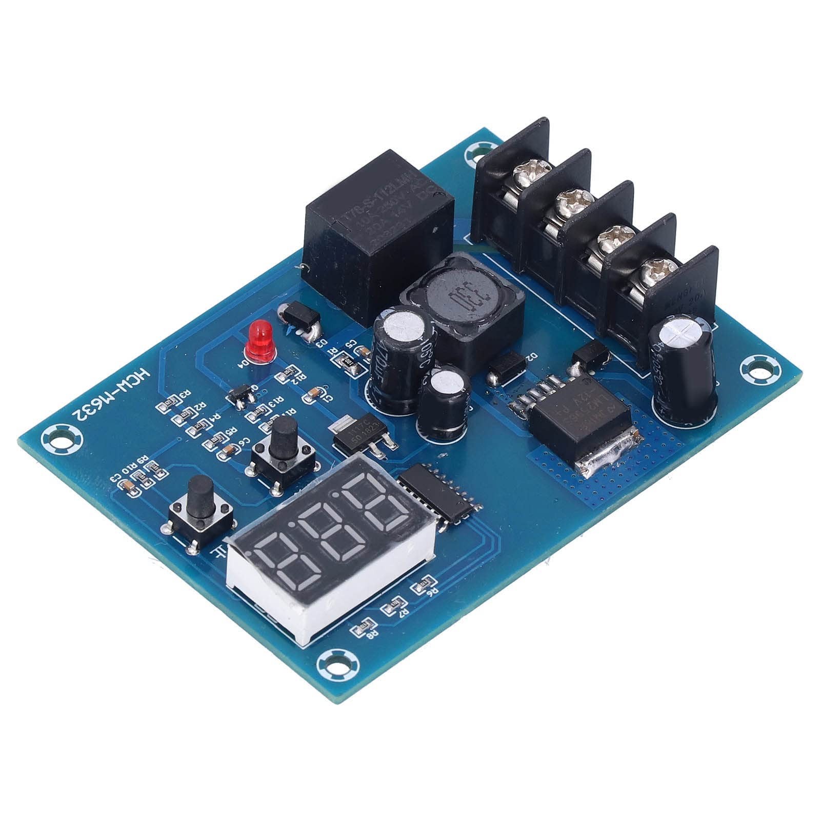
The onboard controls allow the lower and upper charging voltage thresholds to be configured. The LED display provides a convenient way to view battery voltage and adjust the controller without requiring a separate microcontroller.
When configuring the module, first determine the appropriate charging parameters for your battery and charger. Set the lower threshold to the voltage at which you want automatic charging to begin and the upper threshold to the voltage at which the external charger should be disconnected.
Why Use Separate Start and Stop Voltages?
Using separate start and stop thresholds prevents the relay from rapidly switching on and off around a single voltage point.
Battery Low
    |
    v
Charger ON
    |
    |
    | Battery charging
    |
    v
Battery High
    |
    v
Charger OFF
The difference between these thresholds creates a useful control range, sometimes referred to as hysteresis, which provides more stable automatic operation.
No Arduino Required
The XH-M603 is a standalone controller and does not require an Arduino, ESP32, Raspberry Pi, or programming for normal operation.
Once the voltage thresholds have been configured, the onboard circuitry continuously monitors the battery and operates the relay automatically.
Common Applications
- Automatic battery charger control
- 12V battery systems
- 24V battery systems
- Backup battery maintenance
- Workshop charging systems
- DIY battery projects
- Auxiliary power systems
- Solar-related battery projects
- Automatic voltage monitoring
- Electronics and STEM projects
Battery Chemistry Matters
Different battery chemistries require significantly different charging methods and voltage limits. Lead-acid, AGM, GEL, Li-ion and LiFePO4 batteries should not automatically be treated as interchangeable simply because they have a similar nominal system voltage.
Always follow the battery manufacturer's recommended charging voltage, current limits, and charging procedure. Lithium battery systems should also use an appropriate Battery Management System (BMS) where required.
Relay Load Considerations
The onboard relay has a maximum switching capacity. Before connecting a charger, check the relay markings and module specifications to ensure the voltage and current being switched are within its ratings.
For high-current charging systems, the onboard relay can instead be used to control a suitably rated external relay or contactor rather than carrying the full charging current directly.
Important Usage Tips
Confirm polarity carefully before applying power and verify the battery voltage using a reliable multimeter when initially configuring the controller.
The XH-M603 should not be relied upon as the only protection device in a battery system. Appropriate fusing, charger protection, battery protection, and a suitable BMS should be used where required by the application.
Before leaving an automatic charging system unattended, test both the lower and upper thresholds and confirm that the relay reliably starts and stops the charger at the intended voltages.




 Arduino Modules & Sensors
 Battery Compartments
 Component Cases
 Electronics Kits
 Microcontroller Boards
 Project Enclosures
 Shields & Hats
 Tablets
 Laptops
 Laptop Accessories
 CPU (Processor)
 CPU Coolers
 GPU (Graphics)
 HDD/ SSD (Storage)
 MOBO (Motherboard)
 PSU (Power Supply)
 RAM (Memory)
 Keyboard & Mouse Combo
 Keyboards
 Printers
 USB